

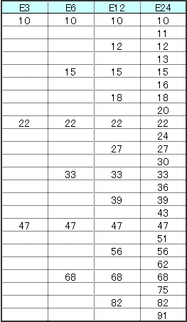
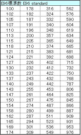
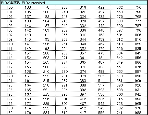
The lineup of resistance does not have round integral value but betwixt like 2.2Ω or 4.7Ω... This is because resistance value is defined by E series, that divides the interval from 1 to 10 into geometric series. E12 series and E24 series are generally used but some resistors under 1% tolerance are available in both E96 values and E192 values. The passive components including resistors use this standard values as significant values and express constant.
E means Exponent and for example, E12 series divides the interval from 1 to 10 into geometric series, that is twelfth root of ten. In logarithmic scale, geometric series is in equal intervals. The values are not round integral values like 2.0 or 3.0, which may makes you bewildered first. At actual desigining step, you will need xx% increase or decrese, which you will feel it easy to use.

The theoretical figure of is rounded to the E12 series which is every other element of the E24 series.
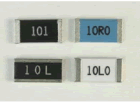
Resistors have the resistance marking in three or four alpha-numerals on the top surface. Some small size resistors have no marking.
3 digits
4 digits
The 1st, 2nd and 3rd digits are significant of resistance shown in E96 and E196. The 4th digit means the multiplier number of zero to follow. R means a decimal point. L means a decimal point of resistance expressed by mΩ.
| Code | A | B | C | D | F | G | J | K | M |
|---|---|---|---|---|---|---|---|---|---|
| Resistance Tolerance |
±0.05% | ±0.1% | ±0.25% | ±0.5% | ±1% | ±2% | ±5% | ±10% | ±20% |
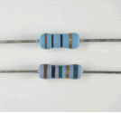
Some lead type resistors indicate the resistance and tolerance by color code.
4 lines:
The 1st and 2nd lines show significant value of nominal resistance, the 3rd line, magnitude. The 4th line means the resistance tolerance.
Ex) Red / Red / Orange / Gold: 22×103Ω±5%→ 22kΩ±5%
5 lines:
The 1st, 2nd and 3rd lines show significant value of nominal resistance, the 4th line, magnitude. The 5th line means the resistance tolerance.
Ex) Yellow / Purple / Green / Red / Brown: 475×102Ω±1% → 47.5kΩ±1%
Recognizing the fist line of the color code is little difficult but the 1st line of 4-line type is closer to the lead wire than the 4th line.
For five-line type, the interval of the 4th and 5th is wider than other space. The 5th line sometimes is wider than other lines.
The size indication of chip resistors are divided into three ways; code, milimeter and inch.
Code indication combining a figure and an alphabet, like 1J, 2A..., this originally means the rated power(1J: 1/16W, 1/10W: 2A, 1/8W: 2B, 1/4W: 2E...). When flat chip resistors were developed initially, the rated power meant the product size. KOA has improved the rated power of each product size, but using the code, 1J, 2A... has been already known as size. So we still use these codes to show the product size.
The size in milimeter and in inch, both are indicated in four figures(five figures exceptionally).
In milimeter size, AABB means L is A.Amm and W is B.Bmm fron the top.
For example, 1608 means L = 1.6mm× W = 0.8mm.
In inch size, CCDD means L is 0.CC inch and W is 0.DD inch from the top.
For example, 0603 means L = 0.06 inch × W= 0.03 inch.
KOA catalogue shows the four figures of inch size code in paranthesis below the letter code, 1J, 2A..., but milimeter size code is widely used in Japan.
Three ways of indication are shown in the table below.
| L mm x W mm | Code (Figure+alphabet) |
Inch Size Code | Milimeter Size Code |
|---|---|---|---|
| 0.4×0.2 | 1F | 01005 | 0402 |
| 0.6×0.3 | 1H | 0201 | 0603 |
| 1.0×0.5 | 1E | 0402 | 1005 |
| 1.6×0.8 | 1J | 0603 | 1608 |
| 2.0×1.25 | 2A | 0805 | 2012(2125) |
| 3.2×1.6 | 2B | 1206 | 3216 |
| 3.2×2.6 | 2E | 1210 | 3226(3225) |
| 5.0×2.5 | 2H(W2H) | 2010 | 5025 |
| 6.3×3.1 | 3A(W3A) | 2512 | 6331(6432) |

